Plate Cleanup Comparison

Brake – Round 6 (Back Plates)

It’s been months since I’ve worked on the Rover. Lot’s of competing interests and importantly, I haven’t had electricity in my shop for 6 months while the building is getting renovated. Fortunately, that project is moving along faster than this one.

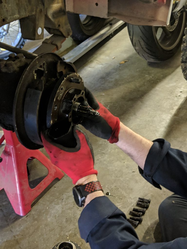
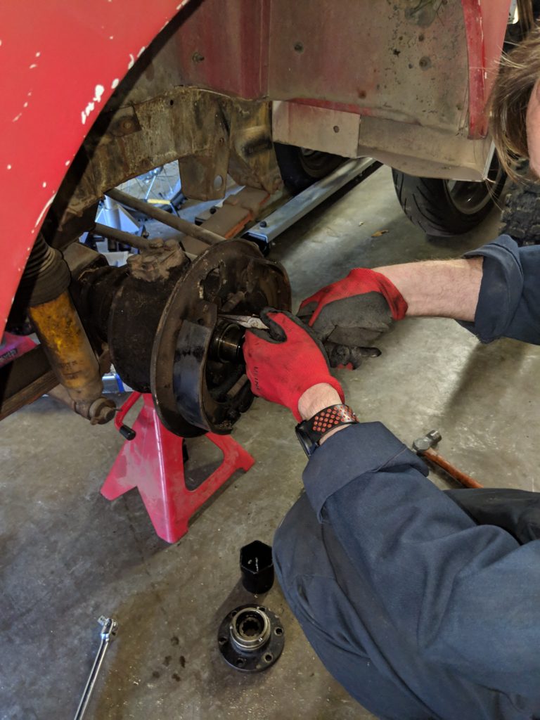
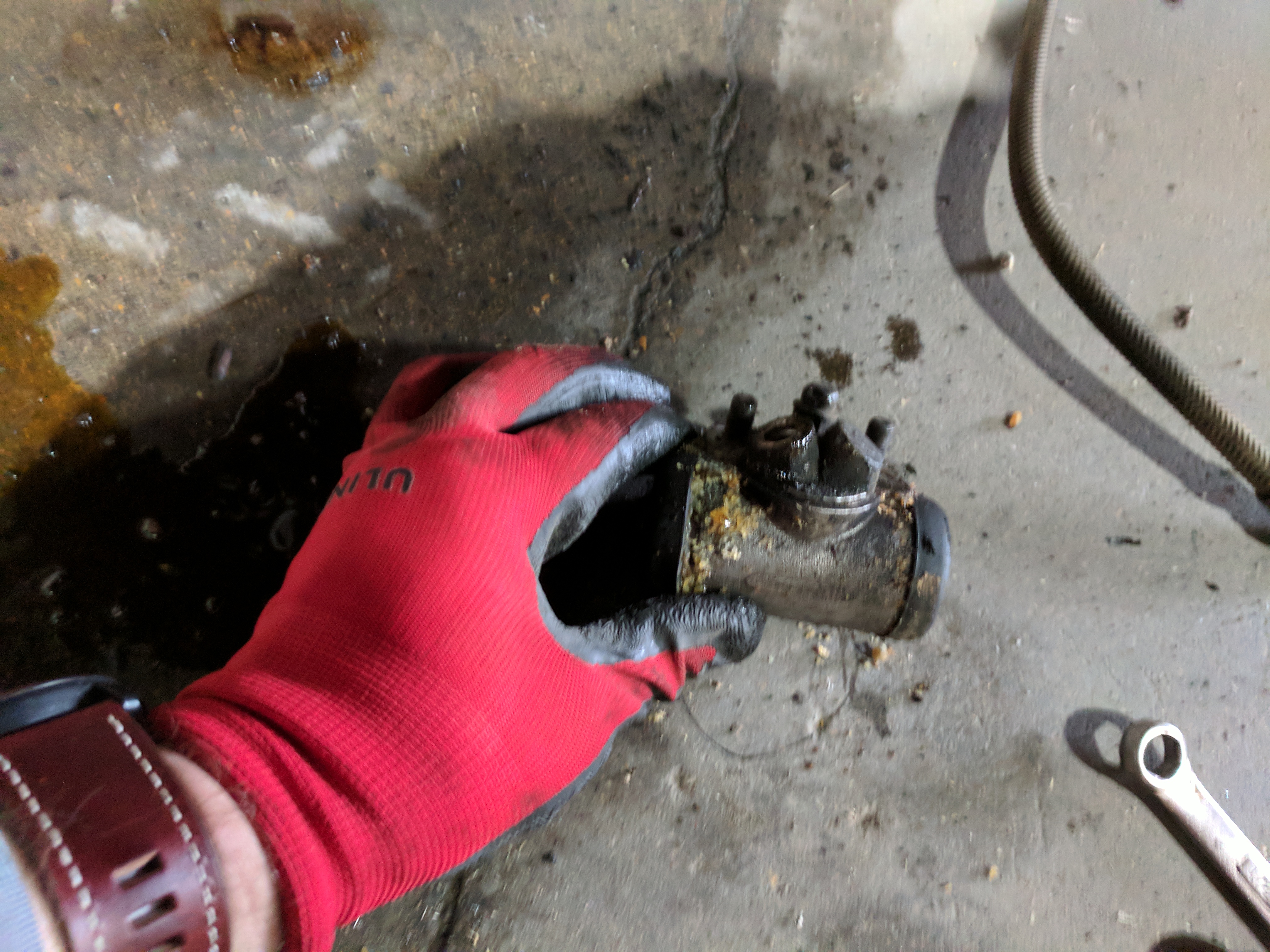
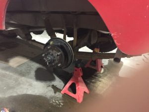
I am not reporting meaningful progress, but I did want to share a few images of the brake back plates. When I pulled them from the Rover, they were caked in grease. That was the good and the bad news. On the plus side, unlike back plates I’ve seen in many other posts, the plates on my Rover are not pitted. Grease has protected the surfaces and they’ve cleaned up nicely.

Cleaning the Parts

The downside was that the grease needed to be removed. I made an attempt to wash the grease off with simple green and some washer and quickly realized that it would neither be easy or quick to clean them up. So off I went to Northern Tool where I acquired a Homak 20 gallon parts cleaner with an integrated pump. I splurged and bought the one that sits on a wheeled cart. That turned out to be a good investment as I’ve moved it around the shop and used it for a variety of clean-up projects now. While a few people warned me away from this cleaner, it has worked well for me.

I coupled the washer with 5 gallons of Von Haas Parts Washer Solvent. While the solvent wasn’t quick, it was effective. I pulled up the parts tray and immersed each back plate in the solvent and let it rest for a day. Then, I brushed off what I could and repeated. The total time spent cleaning the plates was probably only an hour but it took a full week to soften all of the “vintage sludge”.

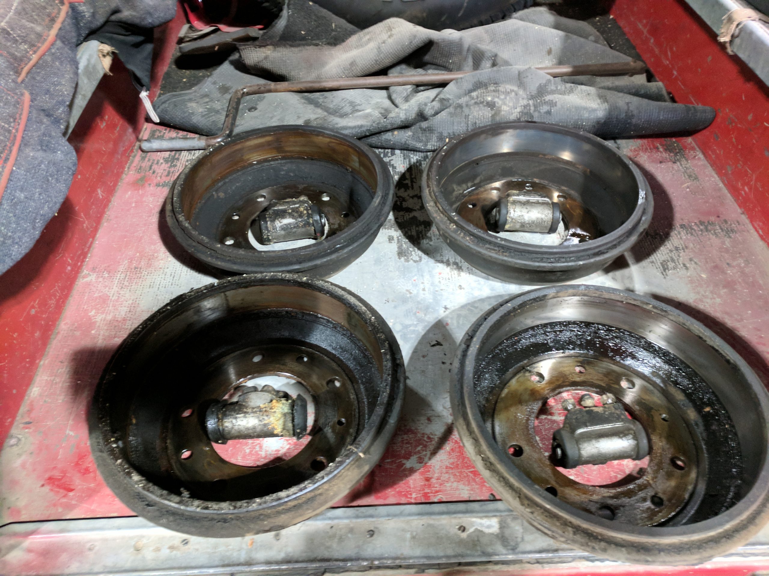
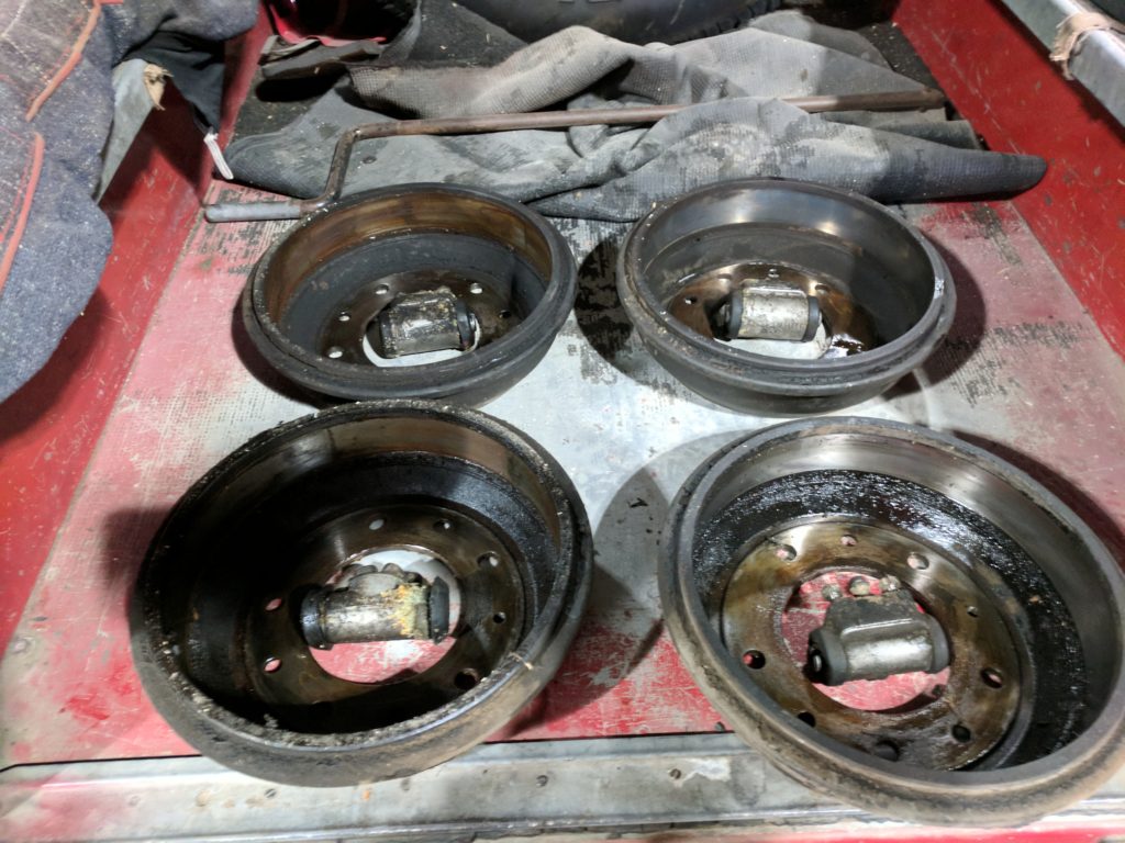
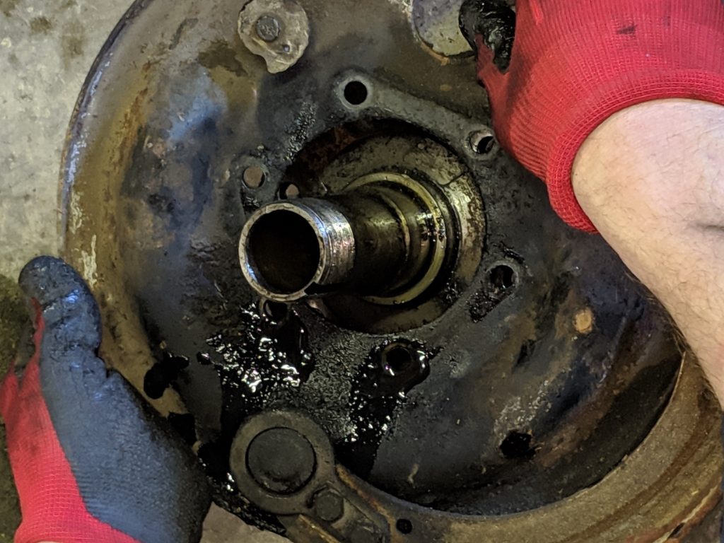
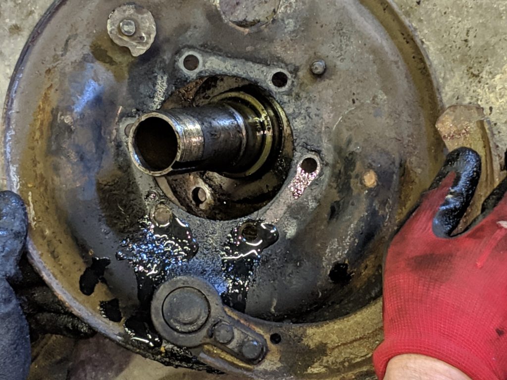
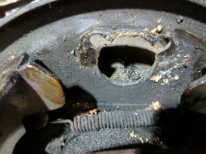
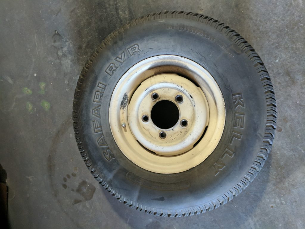
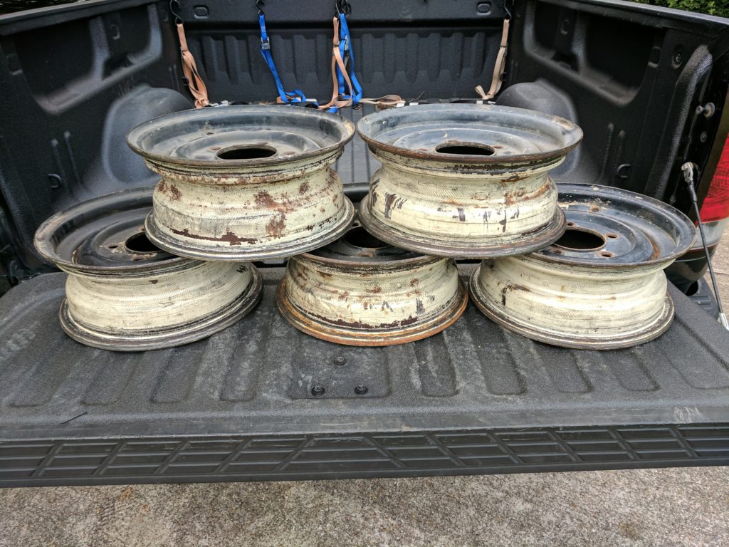
The cleaned up back plates looked really good. As I noted, because of the heavy coating of oil and grease, there was minimal rust and almost no pitting. The stainless steel brush I used to clean them managed to scuff off some paint, but overall as the picture below shows, a little paint would have returned them to a passable state.

De-greased Brake Back PlatesDe-greased Brake Back Plates
De-greased Brake Back Plates

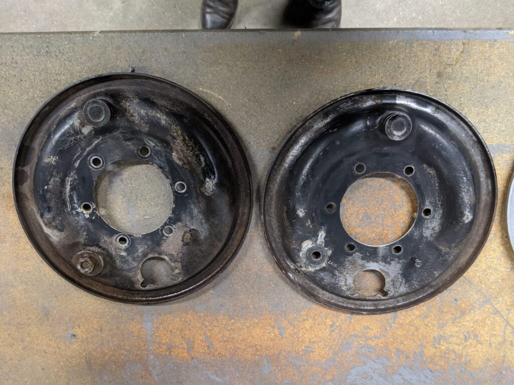
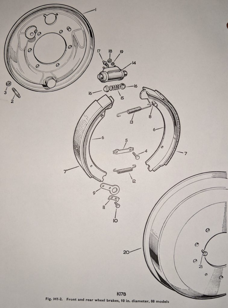
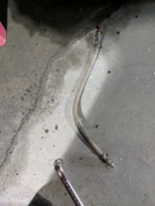
In the picture above, note that I managed to break the adjuster which should appear in the lower left corner of the right back plate. So, replacing the adjusters just got added to the project.
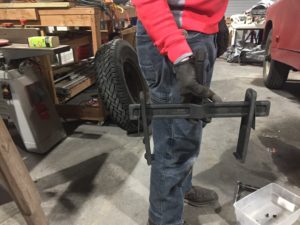
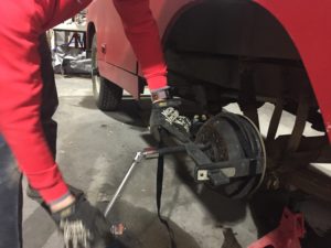
Blasting the Plates

Rather than paint these, I’ve decided to power coat them just like the wheels, That means that they need to be bead blasted and then etched to allow for the new finish. I’ve been taking on one back plate each night as a way to kill some time while everyone is locked in waiting for the Covid-19 crisis to pass. I’m using straight glass beads. For more information on blast media, check out Skat Blast’s website. Glass beads do the job but they’re pretty slow. I am planning to order some of their “Speed Bead” which should cut clean time by a factor of 5. For a comparison of media take a look at their media comparison chart.

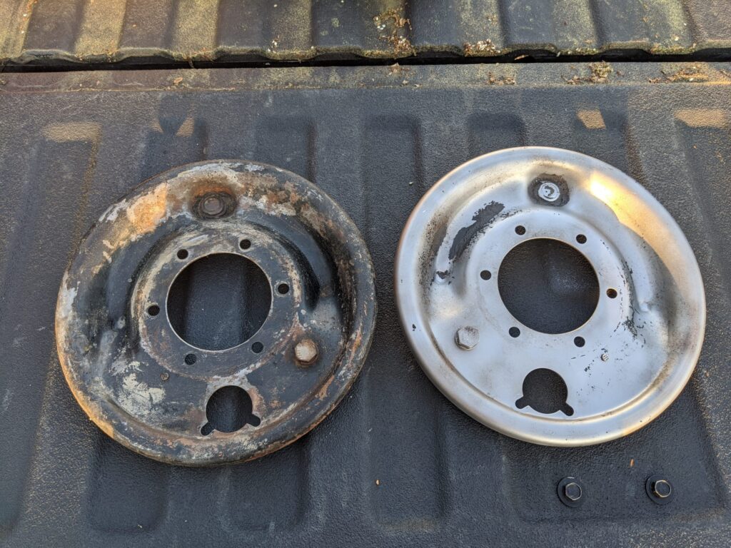
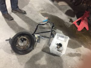
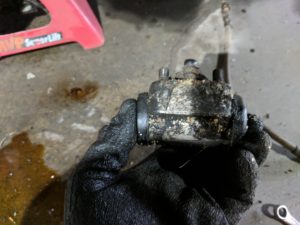
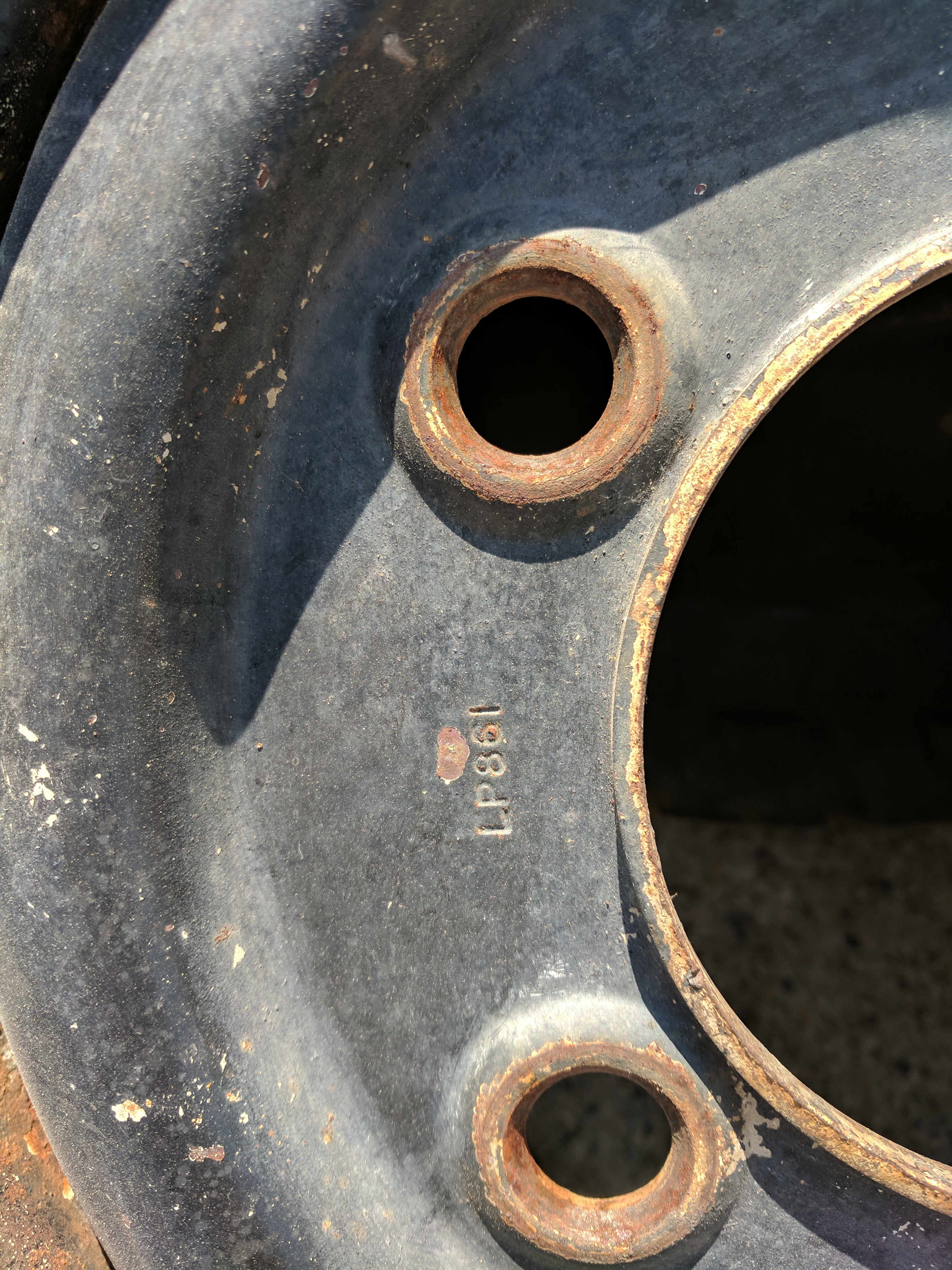
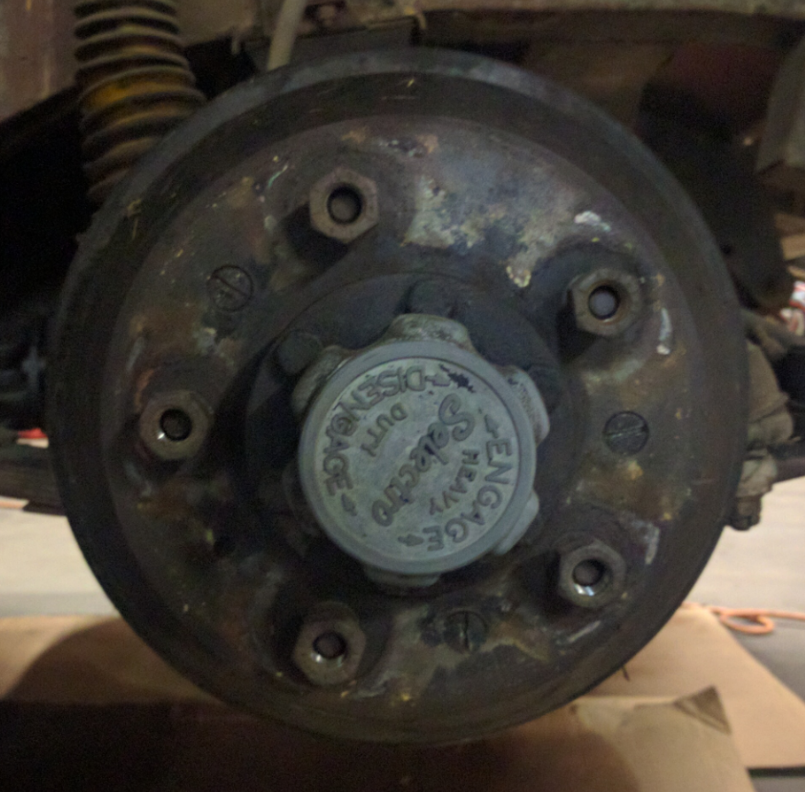
The picture below shows the results from the first bead blasting session. The black spots on the blasted part are actually grease deposits which the glass beads just won’t remove.

Plate Cleanup Comparison

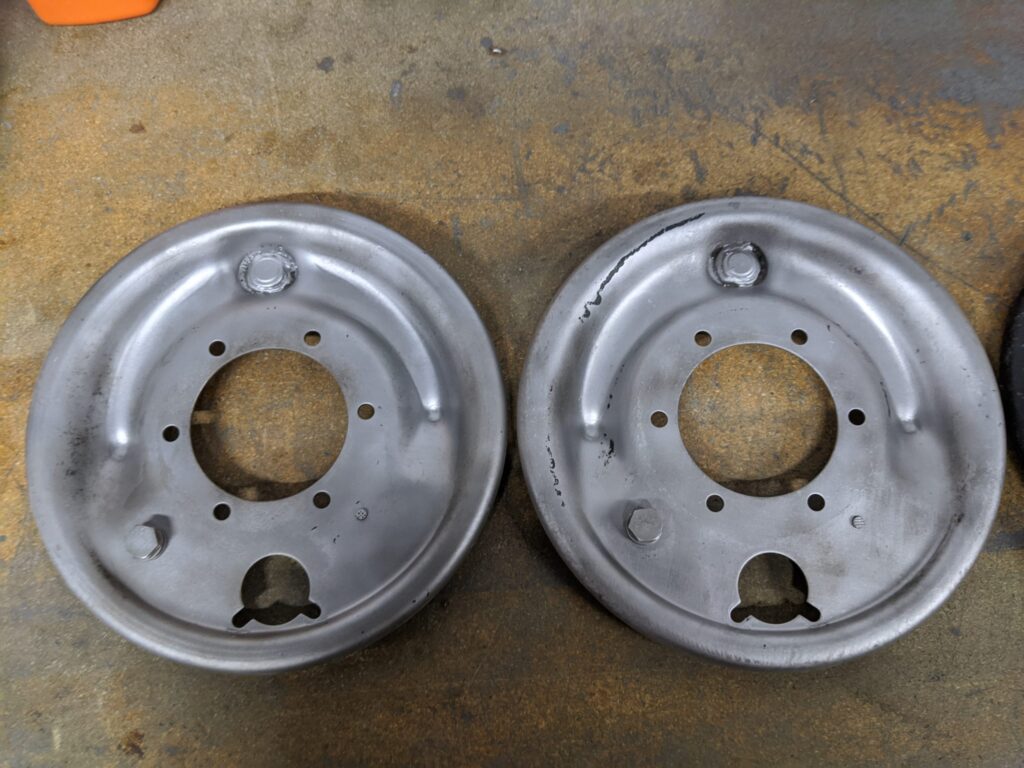
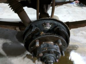
After a follow up trip to the de-greaser, two plates are complete. The results are pretty good. There are a few places where it is obvious that even after trying again, I did not remove 100% of the grease. I’ll drop them in the washer again and then re-blast. Two almost finished plates are shown below.

Bead Blasted Back Plates

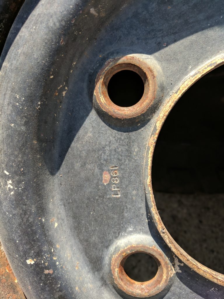
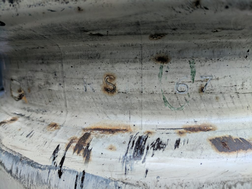
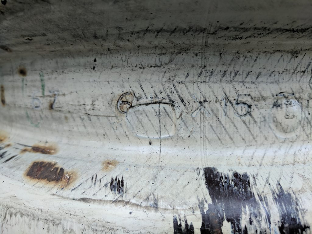
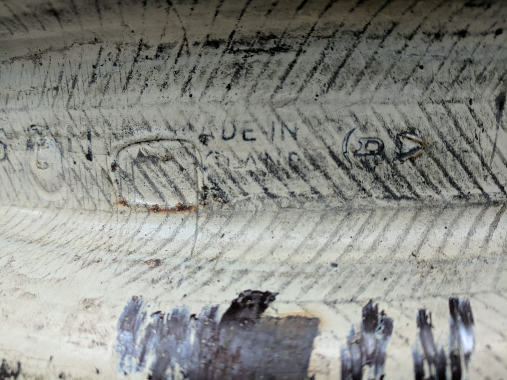
Land Rover Series 2A Brake Back Plate Part Numbers

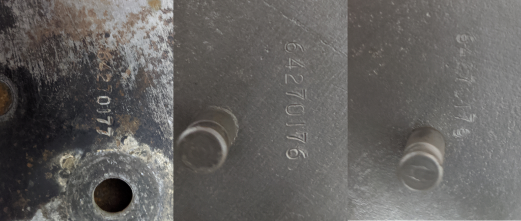
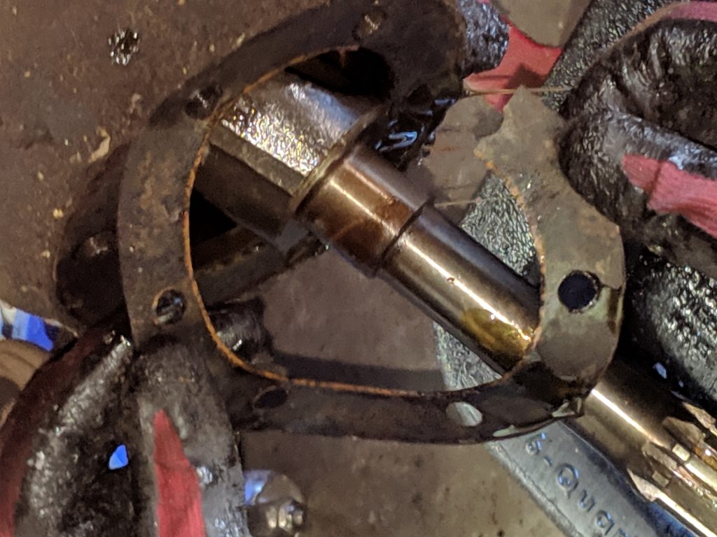
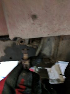
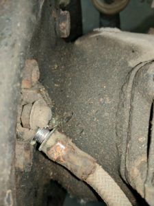
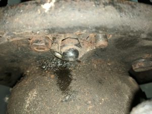
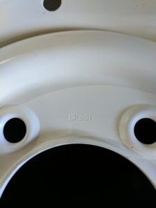
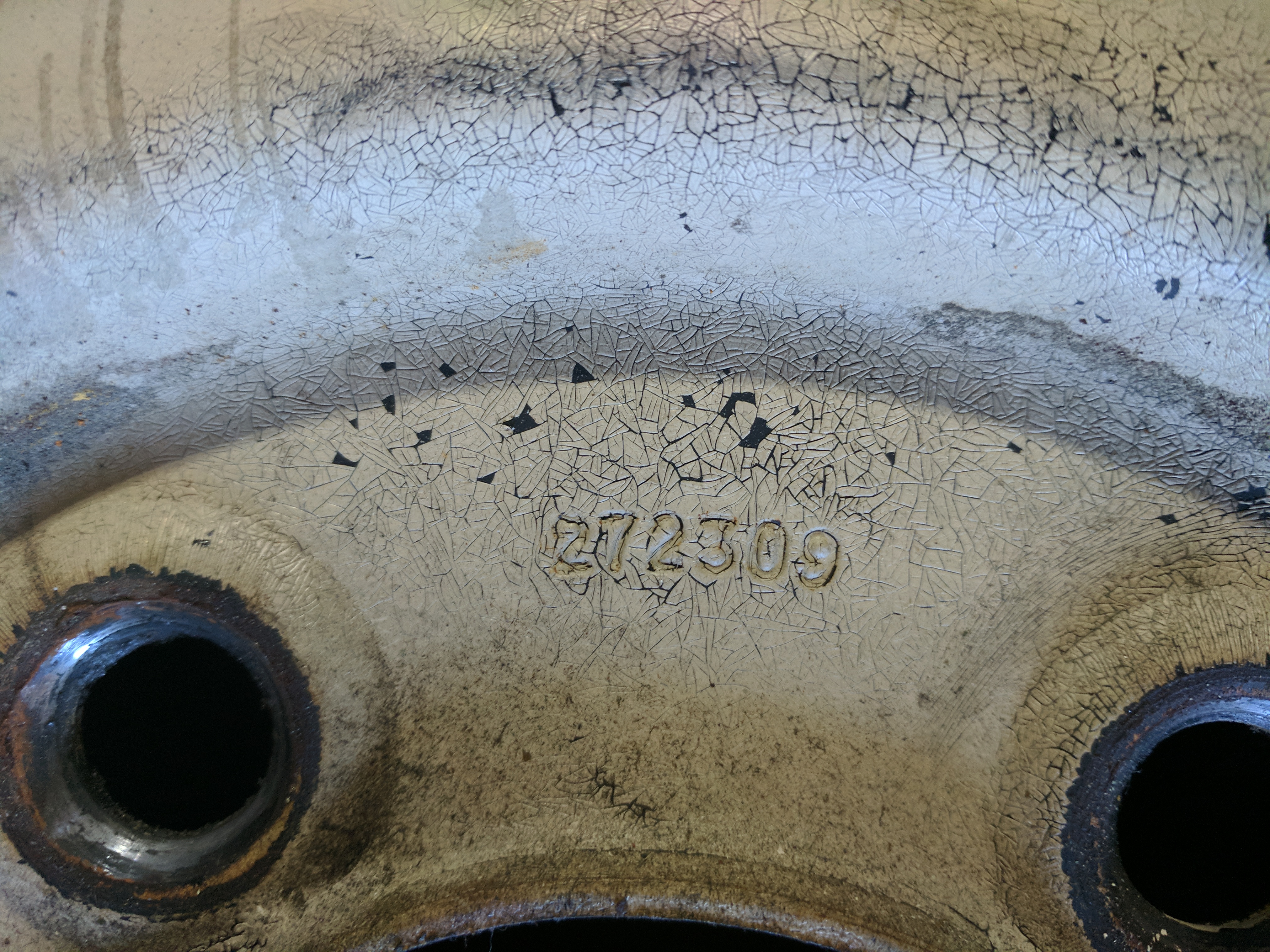
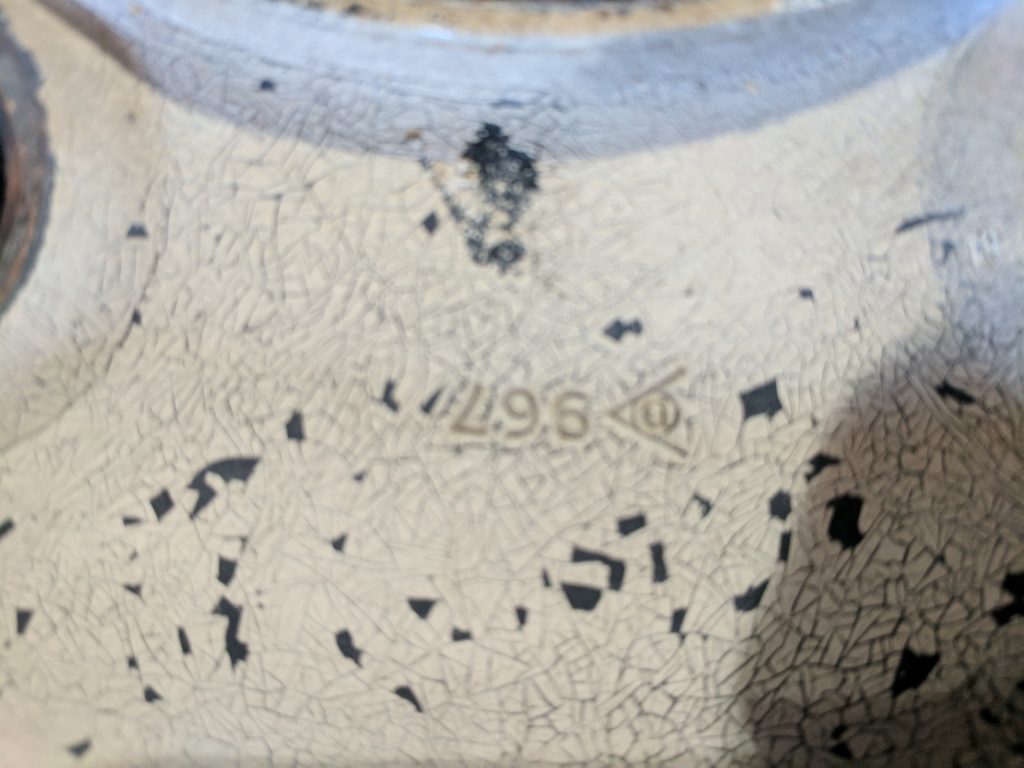
Since the parts are now cleaned up, I was able to locate the factory apply part numbers. The numbers were obviously hand applied. One of the marks is visibly flawed on the last number which appears to have been double struck. There are two part numbers; one for the left and one for the right. The part numbers are: 64270176 & 64270177. The right two images are the same number applied in the same place with two very different results.

Back Plate Part Numbers
4 Brake Drums & 4 Cylinders

Brakes – Round 5

After a thorough review of the brake components, I’ve decided that rebuilding the system is both cost effective and will provide a functional braking solution. It is not a complex job, but for those who are interested Rovers North provides a nice explanation of the process along with useful tips on completing the job.

Drums

What a nightmare. Getting them off was a major headache. See Brakes – Round 3.

4 Drums and 4 Cylinders

4 Drums & 4 Cylinders

One of the three brake drums is damaged, so I sourced an OEM replacement (NOS) on eBay. The remaining brake drums themselves are in tolerance. The plan is to take the drums to my local auto parts store to be turned on their brake lathe. Per the factory manual the tolerances are as follows:

  • 10″ Brakes – Typical on short wheel base Series 2As
    • Standard Diameter: 10in + .004in (254mm + 0,1mm)
    • Reclamation Limit: 0.30in (0,75mm) oversize on diameter

Wheel Cylinders

Since brake fluid is hydroscopic (absorbs water) over time, corrosion in the uncoated parts of the brake system and in particular within the wheel cylinders is a problem. Over time, the expectation is that corrosion is addressed either by honing the cylinders during the rebuild process or by replacing the wheel cylinders. A longer term fix involves pressing a brass sleeve into a bored wheel cylinder. The result is a corrosion resistant interior that can stand up to water absorbed by the brake fluid. The process is quite common in the restoration business and there are a variety of sources that can re-sleeve your cylinders. Based on the advice of a professional car restorer, I will be sending my wheel cylinders and the brake master cylinder to White Post Restorations. Their service requires that you send them your wheel cylinders (drained of fluid) along with their service form. You can expect to receive your restored cylinders in a couple of weeks. The end result is a bit more expensive than replacement parts, but renders a long term solution based upon the factory original parts.

The Rest

The balance of the parts are available from most of the on-line parts suppliers and include brake shoes, springs, and the adjustment bits. I’ve elected to replace all of these parts. I plan to take pictures and log the receipts once the parts are in hand.

Flattening the tabs on the lock washer

Brakes – Round 4 (Breaking down the hubs)

I’m anxious to get the brakes rebuilt so that I can sneak in some summer driving with the Rover before undertaking a more substantial disassembly and restoration. But with the drums off, now is the perfect time to tear the hubs apart, confirm that everything is in good working order and address the visible bits.

Below, I’ve included some pictures from the hub disassembly process. Getting started required a 2 5/16″ “hub nut spanner”. I wanted a version that would let me attach it to a socket wrench (unnecessary) and found a tool designed for a Jeep hub nut on E-Bay for around $5. The tool shown in the picture below worked, but use with a socket wrench was impossible as the spindle reached all the way to the back of the tool making it impossible to insert a socket wrench stub. I will be ordering the correct Rover version which I can now see is longer.

The correct hub nut spanner is shown below. I found this tool – also on EBay – for $7. Versions on specialty parts web-sites ranged from $15 to $30.

More pictures of the hub removal process follow. The assembly uses a number of “lockers” that require you to bend (or unbend in the case of removal) them to retain the bolt. This includes 3 lockers for the 6 backing plate bolts. I also found a very thin paper gasket behind the brake backing plate – but only on one wheel which may have explained why one wheel had accumulated more oil and dirt.

The entire hub assembly diagram is shown below. Once I’me ready to assemble I plan to pay particular attention to the instructions in the factory manual. I’ve included pictures of the three key assembly drawings from my original factory service manuals below.

Rovers North has similarly detailed drawings along with a listing of purchasable parts that will be useful as I plan for the pieces that I will need to purchase rather than restore.

Motor - Passenger Side

A New Motor

With the deflation of the British Pound relative to the US Dollar induced by Brexit, the cost to obtain a high performance engine replacement has dropped dramatically. Just a year ago, the price for ACR’s 2.25 3 main bearing power plus motor was about $4200 USD before options and transportation. The same engine today is available for about $3,300 USD. For many of the die hard Rover fans who think this is still a lot of money for nothing, this post is not for you. For those of us who are looking to achieve something that maintains the integrity of the vehicle while improving drive-ability, read on.

Choosing a replacement motor was a long process. Lots of reading, conversations with friends, and late night debates narrowed my choice to two companies; ACR and Turner Engineering. Based on my research, these two companies were the both highly regarded and possessed extensive experience with 3 main bearing motors. In the end, the approach ACR has taken just resonated with me and my needs and expectations. I’m sure I would be happy with either company’s product.

While I am a reasonably good mechanic with a network of resources capable of doing the required machine work to pull off a solid rebuild, my reasons for turning to ACR are as follows:

  1. I don’t have the benefit of the years of development that ACR has developed working on Land Rovers in general and Series vehicles in particular. Buying ACR’s product ensures that the benefit of the many lessons learned over the years are built in. No need for me to learn by doing. I don’t expect to build another 2.25 3 main bearing motor, so the idea that I will have the opportunity to revisit lessons learned is a bit far fetched and could involve multiple engine removals and installations.
  2. I find the engineering principles espoused by ACR in their friendly exchange with other engine builders and Series 2  experts (https://vidinur.wordpress.com/2013/05/12/everything-about-tuning-the-2-25-petrol-engine-acr-turner-others-perspective/) to be sound and consistent with my objectives. The fact that peak horsepower numbers are reported at 5,000 RPMs doesn’t take away from the basic improvements detailed in that post. More gas + more air + improved flow = better performance across the board. No one in the entire post contested the idea that the ACR engine would outperform the stock 2.25.
  3. I’m not so concerned about building a motor that will last 300,000 or 400,000 miles. 100,000 is good enough for me. This truck isn’t a daily driver and I don’t plan to circumnavigate the globe or cross a continent in this truck. It is a SWB truck best applied to fun weekends in the mud and rocks. In fact, the idea of driving 300,000 miles in the land rover just sounds painful.
  4. I don’t want to swap in a TDI or other alien power plant. In the end, I want something that looks like a ’69 Series 2A; inside and out. Swapping in the ACR Power Plus should be mostly invisible.

After a little back and forth with Roland Marlow at ACR, I’ve settled on a complete 2.5 3MB Power Plus Package. The costs are as follows:

  • Power Plus Engine Package: £ 3195
  • 2.5 L Upgrade: £ 350
  • Surcharge for non-exchange: £ 350
  • Freight (includes clearance & customs): £ 823
  • Total: £ 4,718

The kit includes a stripped motor, a Stage 2 9:1 head, a Power Plus hi torque cam, and SU carb setup. I intend too keep the original motor, hence the core charge.

Other posts worth reading if you’re considering a replacement motor and/or performance modifications:

  • ACR’s website: http://www.automotivecomp.com/
  • Turner Engineering: http://turner-engineering.co.uk/
  • http://forum.landrovernet.com/showthread.php/227275-ACR-put-your-money-where-you-mouth-is
  • http://www.expeditionlandrover.info/engine_conversions.htm

The motor arrived early last week. I’ve included some pictures below:

Motor - Driver Side

Motor – Driver Side

Motor - Aft View

Motor – Aft View

Motor - Passenger Side

Motor – Passenger Side

New SU Carb - Side View

New SU Carb – Side View

New SU Carb

New SU Carb

New SU Carb

New SU Carb

Bad Brake Cylinder

Brakes – Round 3

Today, with some help, I managed to get the brake drums off. The key to success was an OTC 6980 drum puller. The tool wasn’t perfect as the arms were to short to be used as intended, but it did the job. Before i could pull the drums off, I had to remove the three screws that retained the brake drum. Check out my previous post if you want to see the tool I used to remove the screws. Using my home built tool, I managed to remove 9 screws with no damage to the screw head and without using an impact driver. A picture of the drum puller and it in use is provided below.

Drum Puller

OTC 6980 Drum Puller

Note the fact that I’ve placed the bolt in the center of the puller on the head of a bolt that retains the hub. It is intended to be centered on the hub and is fitted with a pin that would have perfectly seated centered the tool. The tool was wide enough for the land rover drums, but the arms were not long enough. Fortunately, the tool also comes with a strap that hold the tool onto the drum and even with the tool off center, it pulled the drum off easily.

Brake Puller in Use

Brake Puller in Use

Removed Brake Drum - Inside View

Removed Brake Drum – Inside ViewOnce the drums were off, I focused on removing the brake cylinders.

No Brake Drum

No Brake Drum

The first step in removing the brake cylinders was to disconnect the brake lines. I setup with the expectation that there would be a lot of brake fluid to catch, but it turns out the brake lines were almost dry. For the front brakes, the flexible brake line needed to be disconnected from the frame first. Then the brake line itslef could be easily detached from the cylinder. Detaching the rear lines was easier as each cylinder was only attached to a fixed hard line.

Front brake line removed

Front brake line removed

Front Brake Line

Front brake line being removed

Front brake line

Front brake line

With the brake lines disconnected, removing each cylinder was accomplished by removing two 1/2″ nuts.

Brake Cylinder Retainers

Brake Cylinder Retainers – One nut removed.

Brake Cylinder Removed

Brake Cylinder Removed

Except for the right front, the brake cylinders were in horrible shape. A few pictures tell the story.

Bad Brake Cylinder

Bad Brake Cylinder

Bad Brake Cylinder

Bad Brake Cylinder

It isn’t surprising that the Rover didn’t stop when you look at the brake cylinders and the results of their failure. The picture below shows just how much fluid accumulated in the brake drum and how that interacted with the dust and debris developed by brake wear.

Result of Failed Brake Cylinder

Result of Failed Brake Cylinder

It took me about three hours to get everything off. Unfortunately, one drum was badly seized and it was damaged during removal. Otherwise, everything else is rebuildable. The removed brake drums and cylinders are shown in the back of the Rover in the picture below.

Brake Parts - Ready for Restoration

Brake Parts – Ready for Restoration

I am planning to send the cylinders to White Post Restorations to have the cylinders rebuilt and sleeved. I could rebuild them myself, but I don’t have the tools to fit them with brass sleeves which will substantially prolong their life and function. Their service is very affordable when you consider that the finished product will outperform both the OEM part (if you can buy them) and typical aftermarket replacements. Once finished, the Rover will be fitted with factory original cylinders that are better than new.

Original 15″ Wheels – LP861 – Progress

In one of my previous posts, I shared some photos of the original factory wheels that came with the Rover. They had been painted several times and were not the correct color. In fact, they had been painted so many times that some of the factory marks were missing. Well, the wheels were blasted and then sent our to be powder coated. After removing all of the layers of paint and grime, the LP861 mark showed through on all 5 wheels. The powder coater didn’t have “limestone” as a color option, so we searched the color book and picked something that looked to be close to limestone.

A close up of one of the wheels and the LP861 mark is shown below

Wheel Mark

Original factory wheel mark – LP861

I also purchased a complete set of bias ply off road tires, shown below. These tires are manufactured by Coker Tire, a company that specializes in vintage tires. The tires are the Super Traxion STAs, size L78-15. You can purchase them direct from Coker or do what I did. I purchased them from Summit Racing. They cost a little more when purchased at Summit but shipping was free. So all in, I saved a few dollars by buying from Summit.

Factory Wheels Plus STA Super Traxion Tires

Wheels and Tires

The last picture shows the tubes that I purchased with the tires. These are also a Coker item purchased through Summit. Technically, I could run these tires without tubes, but they came from the factory with tubes, so we will run tubes in these wheels. I also plan to fit out a set of 16″ wheels (the other set that came with the truck) with BF Goodrich A/T off road tires as an alternative to the 15″ setup.

Wheels and Inner Tube

15″ factory LP861 wheels with inner tube.


Land Rover Part Number 272309

16″ Wheels

The Land Rover came to me on a set of 16″ wheels that the previous owner had purchased. He indicated that he had purchased the 16″ wheels to improve mileage and performance in general. I didn’t get any other information from the owner. My plan is to restore the original 15″ wheels to factory specs and then to put a set of period correct bias ply tires on them. My plans for the 16″ wheels was to finish them in a dark color – perhaps steel gray – and fit them with BF Goodrich Mudders. But after reading a few forums, noting that they appear to be original rims, I may stick with an original finish. To help me decide, I’m trying to learn a little bit more about them. A picture of one of the wheels follows: The entire set was fitted with “modern” tubeless radials.

16" Series 109"Wheel

16″ Series 109″Wheel

What I have learned so far is that the wheels are Land Rover wheels – part number 272309. 3 of the 5 wheels are stamped with this part number (picture below). I’ve found several references to this number which all point to these wheels being from a 109″ Series truck. The wheels are 16″ x 5.5″ with a 1 3/4″ offset.

Land Rover Part Number 272309

Land Rover Part Number 272309

Several of the wheels are also stamped with a Dunlop logo and the number 967 I have been unable to figure out what that mark is. Picture below:

16" Dunlop Mark

16″ Dunlop Mark

Original 15″ Wheels – LP861 / “RS 6×15 Made in England”

Its been a while since I worked on the Rover. Over the summer it sat while I tended to other priorities. Since I had a little free time this weekend, I decided to apply some of that time to getting the Rover back on the road. The brake restoration and addressed in another post, so today I turned my attention to the wheels & tires which will eventually need to go back on.

The truck came to me with two sets of wheels. The set that the Rover was rolling on when it arrived in my shop were 16″ wheels. The previous owner had purchased these along the way to improve the drive-ability of the truck. But he also sent along what he reported to be the original 15″ wheels. My own research suggests that the original wheel size would have been 15″ as Land Rover switched to 15″ wheels in 1969 on what the factory called the “Federal 88 inch” models. The “Federal 88 inch” introduced a series of safety related updates that were mandated by US federal regulations. The switch from 16″ wheels (standard issue prior to 1969) to 15″ was attributed to better availability of 15″ tires in the US.

The 15″ wheels are shown above. 3 of the 5 are stamped with the code LP861 – shown below. The other 2 have no similar marking. The LP861 marking appears to be common to Land Rover 15″ x 6″ factory wheels as I’ve found several references on the web for Series IIa wheels manufactured after 1967 being marked this way.

Today we took the 15″ wheels to the tire shop to remove and dispose of the old tires. The tire shop also removed all wheel weights and the valves. While only 3 of 5 wheels were marked as LP861 on the face of the wheel, all 5 were similarly stamped inside. Each wheel was stamped “RS”, then “67”, then “6 x 15”, then “MADE IN ENGLAND”, and finally a Dunlop logo as shown below. From this I am assuming that Dunlop was the OEM wheel manufacturer for Land Rover for at least the 6″ x 15″ wheels.

Land Rover 15" Wheel Stamp RS

Land Rover 15″ Wheel Stamp “RS” and “67”


Land Rover Wheel Stamp "6 x 15"

Land Rover Wheel Stamp “6 x 15”


Land Rover Wheel Stamp "Made in England"

Land Rover Wheel Stamp “Made in England”

By the time I took possession of the Rover, the original 15″ wheels had been painted black. With the tires removed, the original “limestone” finish is revealed. The wheels are now ready for a trip to the powder coat shop to get stripped and finished in the factory color.

15" Bare Land Rover Wheels - LP861

15″ Bare Land Rover Wheels – LP861


Brakes – Round 2

Tonight I started to tackle the restoration of the brake system. My goals were simple, get the brakes disassembled so that I could evaluate all of the parts. Well, easier said than done.

My first challenge was removing the drums. Each drum is retained via 3 flat head screws. I tackled the right front wheel first and approached each screw with a standard (large) flat head screw driver – no luck. The screwdriver failed to turn any of the three screws and even though it was a very large screw driver, the blade was too small to grab the length of the slot. Instead the blade rotated slightly putting all of the turning pressure on the corners of the blade.

Since I didn’t want to strip the heads of the screws, I retreated to the internet for advice. There were plenty of videos and articles to refer to, but most seemed content to destroy the screw heads as long as the fasteners came out. Manual impact screwdrivers were popular options as were chisels. But each of these methods risked stripping the head. After speaking with my father for a while about the various options available to me, I decided to create my own tool that would fit snuggly in the slot and allow me to use a rachet to apply more rotational force while concurrently holding the tool in the slot.

The donor component for my tool was a beat up chisel that was in my drawer of chisels that had been donated to me somewhere along the way. It had a hex handle (perfect for mating with a socket), it was wider than the screw heads, and its blade was gnarly making its usefulness as a chisel minimal at best. With my bench grinder, I set out to form the tool I needed. I made multiple attempts at shaping the blade resulting in a tool that fit well. To make the blade fit, I notched the chisel until it was the correct length and then shaped the blade to arrive at the width that I needed. The shape of the wheel on the bench grinder initially resulted in a shape that was too tapered which allowed the tool to slip. So I reduced the taper using the side of the wheel and a little freehand work. The result is shown here.

Note the change in the taper at the end. While not a perfect rectangle, the shape was close enough to provide a solid lock with the screw slot and to distribute the turning force across the length of the screw. The fit is snug enough that setting the blade required a light tap with the palm of my hand to get it seated. While it won’t win any beauty contests, once fully inserted, the tool turned each screw out easily with no damage to the screw face.

The rest of my evening was spent trying to remove the drum itself, unsuccessfully. Most articles recommended beating the edge of the drum with a rubber mallet while rotating the drum. I tried this method without success. Some other guides recommended inserting a screw in a threaded hole on the face of the drum. The screw was intended to push the drum away from the backer, this method failed as well. Finally, I had hoped that I could accomplish the task with a gear puller. Unfortunately, my largest gear puller was just a little too small to grip the hub.

So, at the end of two hours, the only thing I had accomplished was removing three screws from the face of the front right brake drum.

Brakes – Round 1

When I bought the Land Rover, during the test ride, the previous owner indicated that it would pull to the right a bit when the brakes were applied. He figured it needed a brake rebuild and was he ever correct!

I wasn’t too concerned with how it drove when I was buying the truck. I was focused on confirming that it was complete and that the body and frame were in good condition. All mechanical systems were assumed to need repair or restoration. As the previous owner explained, it does pull to the right when the brakes are applied. But that is less important than the fact that the truck doesn’t stop well and in its current condition would not pass a basic safety inspection. This post is the first of a series of posts where I take on rebuilding the brake system to get me one step closer to being able to use the Rover for something other than a tool stand in my shop.

Before starting this project, I did a lot of looking at disk brakes. There are several conversions out there. The ones I’ve found are listed below.

I found reference to a few others that may still be available or were available in the past, but the 4 listed above had active websites that appeared to be current. Note that the Heystee and Forbyn kits are limited to replacement swivels and still require the purchase of discs, calipers, and the other components required to make them fully functional. Rovers North sells a full kit which I believe is based on swivels manufactured by someone in the UK or Europe. The Torrel and Zeus kits appear to be complete and include the required calipers and brake rotors. The cost of the parts alone is at least $1200 depending on which kit is selected and more depending on what other supporting upgrades/purchases are required.

With the above in mind, I’ve decided that before I invest in disc brakes, I need to assess the condition of the drum brakes on the truck. The factory drums might do a fine job if they are restored to original working condition. Of course, that may be expensive as well. If everything needs to be replaced, a disc brake conversion might not be much more expensive. The only way to know is to take apart what I have and evaluate each component to determine what needs to be replaced and what can be repaired.

The next post will document the disassembly of the brakes. I am assuming that I’m in for a lot more than the wearing components. The goal here is to determine what parts I need to buy to complete the job so that I can determine which direction I should go.